

IB-0210
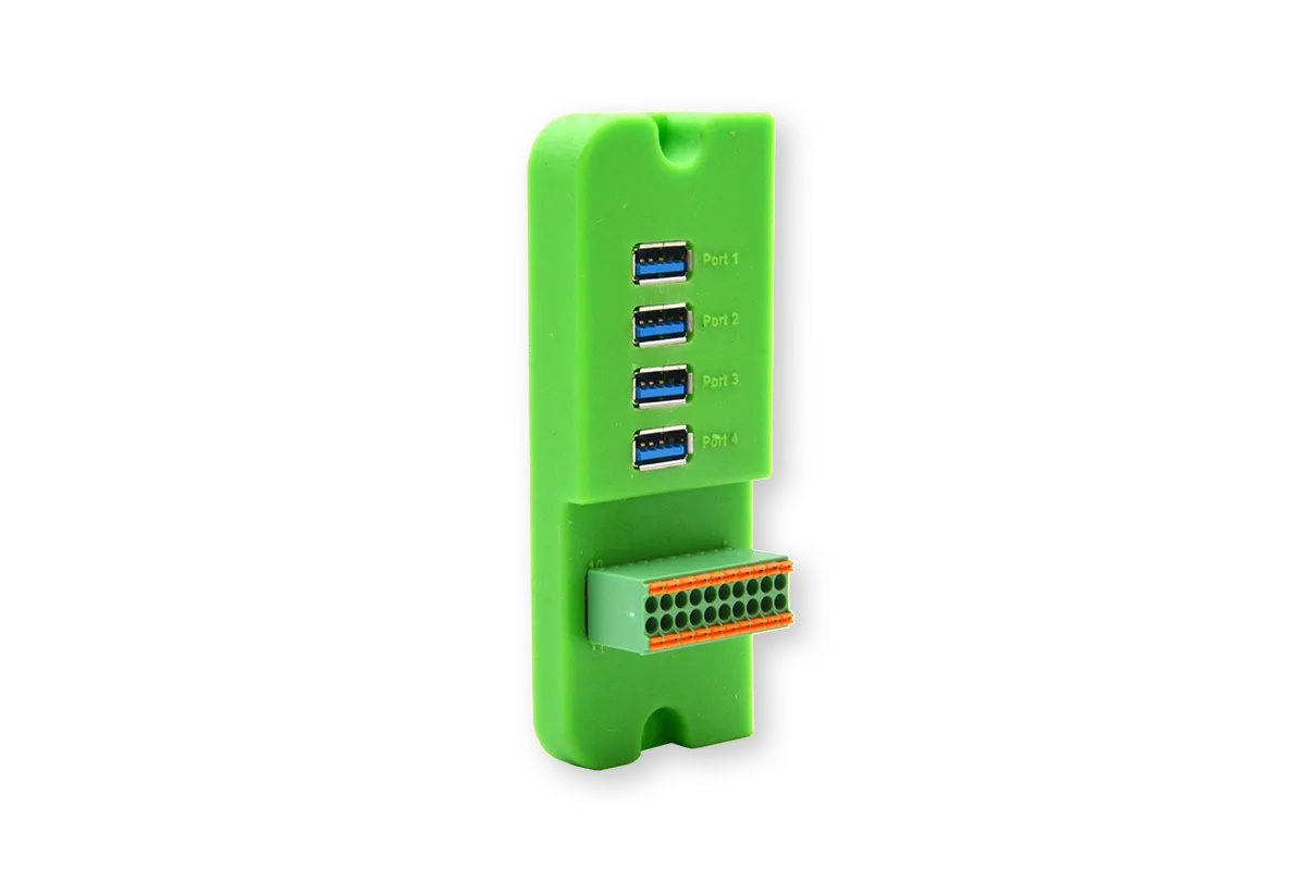
An interface module for up to 4 USB3.0 cameras and with digital I/O.
Description
This module can be used in applications where USB3.0 is required and some input/output interfacing is necessary. The module has 4 USB3.0 standard-A ports and has an internal USB3.0 hub controller on the module which support following speed modes:
- Super Speed (SS) - 5 Gbps
- High Speed (HS) - 480 Mbps
- Full Speed (FS) - 12 Mbps
- Low Speed (LS) - 1.5 Mbps
This allows you to stream up to 4 cameras in high resolution and a high frame rate. All ports are backwards compatible with USB2.0.
The module has 4 Digital Outputs (DO) and 4 Digital Inputs (DI). Both are 24VDC compatible and optical isolated from the BLOX device. These I/O can used to interface with a remote system such as a PLCs or other industrial systems.
Block diagram
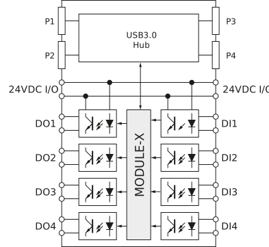
The above diagram shows the block diagram of the interface module. There are 3 main parts:
- USB3.0 Hub
- Digital Output circuits
- Digital Input circuits
The USB3.0 Hub is connected to the BLOX USB3.0 port. This way, the BLOX USB3.0 port is extended with 4 USB3.0 ports P1…P4.
The digital outputs and inputs are galvanic isolated from the BLOX. This allows you to use 2 different power supplies: one for the BLOX (24VDC) and the other for the I/O (24VDC I/O).
Connections
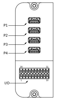
P1 to P4 port
The Px are the USB3.0 ports and compatible with the USB3.0 standard-A.
| Pin# | Pin Name | Description |
|---|---|---|
| Shell | Shield | Metal housing |
| 1 | VBUS | Power |
| 2 | D- | USB 2.0 differential pair - negative signal |
| 3 | D+ | USB 2.0 differential pair - positive signal |
| 4 | GND | Ground for power return |
| 5 | StdA_SSRX- | SuperSpeed receiver differential pair - negative signal |
| 6 | StdA_SSRX+ | SuperSpeed receiver differential pair - positive signal |
| 7 | GND_DRAIN | Ground for signal return |
| 8 | StdA_SSTX- | SuperSpeed transmitter differential pair - negative signal |
| 9 | StdA_SSTX+ | SuperSpeed transmitter differential pair - positive signal |
I/O Port
| Description | Pin Name | Pin# | Pin# | Pin Name | Description |
|---|---|---|---|---|---|
| I/O Power Supply + | 24V I/O | 1 | 20 | 24V I/O | I/O Power Supply + |
| I/O Power Supply - | 0V I/O | 2 | 19 | 0V I/O | I/O Power Supply - |
| Output Channel 1 | OUT 1 | 3 | 18 | IN 1 | Input Channel 1 |
| I/O +24V | 24V I/O | 4 | 17 | 24V_I/O | I/O +24V |
| Output Channel 2 | OUT 2 | 5 | 16 | IN 2 | Input Channel 2 |
| I/O +24V | 24V I/O | 6 | 15 | 24V_I/O | I/O +24V |
| Output Channel 3 | OUT 3 | 7 | 14 | IN 3 | Input Channel 3 |
| I/O +24V | 24V I/O | 8 | 13 | 24V_I/O | I/O +24V |
| Output Channel 4 | OUT 4 | 9 | 12 | IN 4 | Input Channel 4 |
| I/O +24V | 24V I/O | 10 | 11 | 24V_I/O | I/O +24V |
Accessing I/O Ports
We are developing a python library for accessing the I/O Ports, however this library is not yet available. For now, you can access the I/O Ports through the file system with the commands below.
For MX1030-x (Xavier NX)
- The table below shows the relationship between the GPIO numbers and the DI/DO ports. You need those GPIO numbers to access the ports:
| Port | GPIO # |
|---|---|
| DO1 | 419 |
| DO2 | 264 |
| DO3 | 418 |
| DO4 | 266 |
| Port | GPIO # |
|---|---|
| DI1 | 421 |
| DI2 | 419 |
| DI3 | 264 |
| DI4 | 265 |
- First we need to make the GPIO pins available to the fs:
$ sudo echo 417 > /sys/class/gpio/export $ sudo echo 420 > /sys/class/gpio/export $ sudo echo 418 > /sys/class/gpio/export $ sudo echo 424 > /sys/class/gpio/export $ sudo echo 421 > /sys/class/gpio/export $ sudo echo 419 > /sys/class/gpio/export $ sudo echo 264 > /sys/class/gpio/export $ sudo echo 265 > /sys/class/gpio/export - Second, we need to configure the port direction correctly:
$ echo out > /sys/class/gpio/gpio417/direction $ echo out > /sys/class/gpio/gpio420/direction $ echo out > /sys/class/gpio/gpio418/direction $ echo out > /sys/class/gpio/gpio424/direction $ echo in > /sys/class/gpio/gpio421/direction $ echo in > /sys/class/gpio/gpio419/direction $ echo in > /sys/class/gpio/gpio264/direction $ echo in > /sys/class/gpio/gpio265/direction - Finally, you can control the I/O ports through the value property:
# For DI1
$ cat /sys/class/gpio/gpio421/value
0

# For DO1
$ echo 1 > /sys/class/gpio417/value