

IB-0310
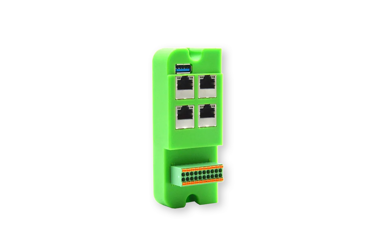
An interface module for up to 4 PoE IP cameras combined with digital I/O.
Description
The IB-0310 is ideal for camera vision applications that require high throughput and Power-over-Ethernet (PoE). Additionally there are 4 digital outputs (DO) and 4 digital inputs (DI) that can be used to interface with other systems for application control.
The module has an integrated PoE PSE Type 2 supply, which provides 30W at each connector. This eliminates the need for an external PoE injector or PoE switch. To be able to use the PoE, the BLOX platform need to be powered with 48V.
Each Ethernet port is separated with its own MAC address, to ensure each camera to stream at maximum throughput of 100Mbps.
The module has 4 Digital Outputs (DO) and 4 Digital Inputs (DI). They are galvanically isolated and require an external power supply with a range from 12V to 40V. The inputs and outputs will be These I/O can used to interface with a remote system such as a PLCs or other industrial systems.
Block diagram
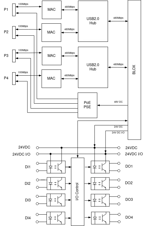
The block diagram above shows the 5 main parts:
- USB2.0 Hubs
- 4 MAC & PHY
- PoE PSE
- Digital Output circuits
- Digital Input circuits
The 4 100Mbps Ethernet connections are spread over 2 USB2.0 Hubs. These hubs are connected to the USB3.0 interfaces of the BLOX. Each Ethernet connection has its own MAC or Media Access Controller. This results in 4 hardware separated connections for maximum throughput of 100Mbps.
A PoE PSE or Power-over-Ethernet Power Sourcing Equipment Type 2 provides 30W at each connector.
The digital outputs and inputs are galvanic isolated from the BLOX. This allows you to use 2 different power supplies: one for the BLOX (24VDC) and the other for the I/O (24VDC I/O).
Connections
P1 to P4 port
The P1..P4 are RJ45 connectors of the 10/100Mbits Ethernet ports.
Each connector hast 2 status LEDs available:
- Link status - Green LED
- Activity status - Orange LED
The P1..P4 ports RJ45 connector with standard pin out:
| Pin# | Pin Name | Description |
|---|---|---|
| 1 | TxRx A + | Bi-directional pair A + |
| 2 | TxRx A - | Bi-directional pair A - |
| 3 | TxRx B + | Bi-directional pair B + |
| 4 | TxRx C + | Bi-directional pair C + |
| 5 | TxRx C - | Bi-directional pair C - |
| 6 | TxRx B - | Bi-directional pair B - |
| 7 | TxRx D + | Bi-directional pair D + |
| 8 | TxRx D - | Bi-directional pair D - |
I/O Port
| Description | Pin Name | Pin# | Pin# | Pin Name | Description |
|---|---|---|---|---|---|
| I/O Power Supply + | 24V I/O | 1 | 20 | 24V I/O | I/O Power Supply + |
| I/O Power Supply - | 0V I/O | 2 | 19 | 0V I/O | I/O Power Supply - |
| Output Channel 1 | OUT 1 | 3 | 18 | IN 1 | Input Channel 1 |
| I/O +24V | 24V I/O | 4 | 17 | 24V_I/O | I/O +24V |
| Output Channel 2 | OUT 2 | 5 | 16 | IN 2 | Input Channel 2 |
| I/O +24V | 24V I/O | 6 | 15 | 24V_I/O | I/O +24V |
| Output Channel 3 | OUT 3 | 7 | 14 | IN 3 | Input Channel 3 |
| I/O +24V | 24V I/O | 8 | 13 | 24V_I/O | I/O +24V |
| Output Channel 4 | OUT 4 | 9 | 12 | IN 4 | Input Channel 4 |
| I/O +24V | 24V I/O | 10 | 11 | 24V_I/O | I/O +24V |
Accessing I/O Ports
We are developing a python library for accessing the I/O Ports, however this library is not yet available. For now, you can access the I/O Ports through the file system with the commands below.
For MX1030-x (Xavier NX)
- The table below shows the relationship between the GPIO numbers and the DI/DO ports. You need those GPIO numbers to access the ports:
| Port | GPIO # |
|---|---|
| DO1 | 417 |
| DO2 | 420 |
| DO3 | 418 |
| DO4 | 424 |
| DI1 | 421 |
| DI2 | 419 |
| DI3 | 264 |
| DI4 | 265 |
- First we need to make the GPIO pins available to the fs:
$ sudo echo 417 > /sys/class/gpio/export $ sudo echo 420 > /sys/class/gpio/export $ sudo echo 418 > /sys/class/gpio/export $ sudo echo 424 > /sys/class/gpio/export $ sudo echo 421 > /sys/class/gpio/export $ sudo echo 419 > /sys/class/gpio/export $ sudo echo 264 > /sys/class/gpio/export $ sudo echo 265 > /sys/class/gpio/export - Second, we need to configure the port direction correctly:
$ echo out > /sys/class/gpio/gpio417/direction $ echo out > /sys/class/gpio/gpio420/direction $ echo out > /sys/class/gpio/gpio418/direction $ echo out > /sys/class/gpio/gpio424/direction $ echo in > /sys/class/gpio/gpio421/direction $ echo in > /sys/class/gpio/gpio419/direction $ echo in > /sys/class/gpio/gpio264/direction $ echo in > /sys/class/gpio/gpio265/direction - Finally, you can control the I/O ports through the value property:
# For DI1
$ cat /sys/class/gpio/gpio421/value
0

# For DO1
$ echo 1 > /sys/class/gpio417/value